
Using CAD Attribute Manager
You can use CAD Attribute Manager to enter the appropriate attribute layers and names as specified in the CAD drawing for each tabbed entity (for example: Building, Floor, Room, Site, and Zone).
Attribute layers and names can be updated when the drawing standard changes. All the building attribute blocks on the drawing must be on the same layer, and the user-defined name must be consistent across all drawings. It is recommended that all attributes within the block are displayed on the same layer as the block is inserted.
Navigate to Functions > CAD > CAD Attribute Manager.
The CAD Attribute Manager window is displayed.

Enter the relevant attributes specified in the CAD drawing for each tabbed entity, building, floor, room, site, and zone.
For each tab the minimum requirement is for the 'Drawing Layer' and 'Unique Name' to be specified as these direct the system to which layer the information will be on and the unique attribute for the building, floor or room entity. All the other attributes are optional and dependant on the information that is required to be synchronised.
The fields on each Attribute tab are described in the following table:
This column… | Holds this information... |
|---|---|
Database Field | The database field. |
Attribute Value | The value associated with the relevant database field. |
Direction | The direction used by the CAD Synchronisation process. Select from:
The CAD synchronisation process will only run with 'From Drawing'. The 'To Drawing' direction is currently unused but is intended for future use. While this option appears enabled and can be selected, it contains no functionality. |
Locked | Whether the synchronisation direction is locked. |
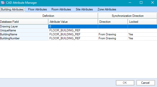
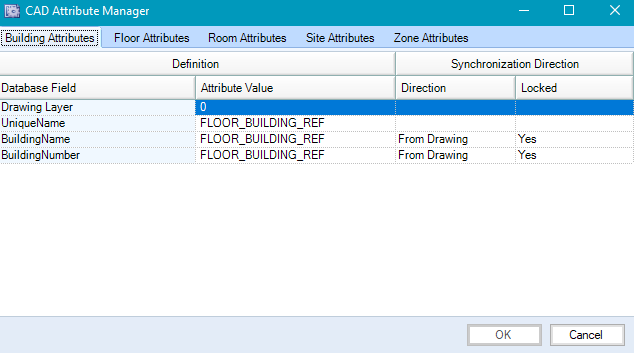
Specify building attributes with the Building Attributes tab.
The database fields on the Building Attributes tab are as follows:
Drawing Layer - used by the synchronisation routine to identify which layers of the drawings contain the relevant attributes (for example A400_ROOMAREAS)
You must not leave spaces between layers added to the Drawing Layer field. The synchronisation process will fail for drawings that contain spaces.
UniqueName - used by the synchronisation routine to match the building, floor, room, site, or zone between the drawing and K2 (for example ESTABLISHMENT_NO,BLOCK_NO with ESTABLISHMENT_NO, containing the property reference number and BLOCK_NO, containing the building number)
The synchronisation routine expects a strict hierarchy between the levels. This hierarchy is expressed in the reference data by stacking the attributes in the unique name field as a comma-separated list.
BuildingName
BuildingNumber
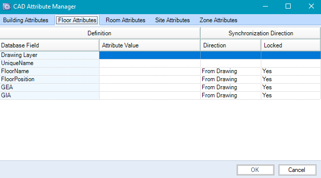
To specify Floor attributesSelect the Floor Attributes tab.
The Floor Attributes tab is displayed.
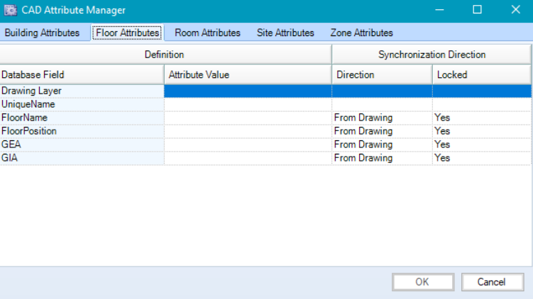
The database fields on the Floor Attributes tab are:
Drawing Layer
UniqueName
FloorName
FloorPosition
GEA
GIA
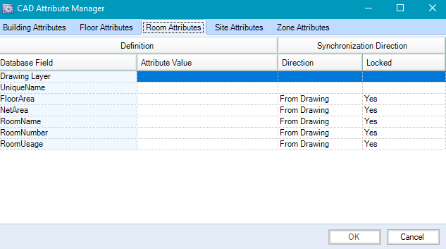
To specify Room attributes
Select the Room Attributes tab.
The Room Attributes tab is displayed.

The database fields on the Room Attributes tab are:
Drawing Layer
UniqueName
FloorArea
NetArea
RoomName
RoomNumber
RoomUsage
To specify Site attributes
Select the Site Attributes tab.
The Site Attributes tab is displayed.
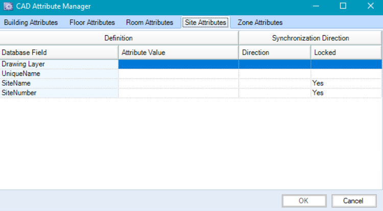
The database fields on the Site Attributes tab are:
Drawing Layer
UniqueName
SiteName
SiteNumber
To specify Zone attributes
Select the Zone Attributes tab.
The Zone Attributes tab is displayed.

The database fields on the Zone Attributes tab are:
Drawing Layer
UniqueName
ZoneArea
ZoneName
ZoneNumber
ZoneTypeID
Click OK.
CAD Attribute Manager examples:
Adding a multiple-layer CAD setup in the UniqueName field
Using data from K2 to set attribute layers
The CAD Synchronisation process searches each block in the drawing for the attributes defined in the Attribute Manager. If any of the required attributes are in different blocks then the attributes in the unique name field need to be defined as global.
To add a multiple-layer setup in CAD Attribute Manager:
Navigate to Functions > CAD > CAD Attribute Manager.
The CAD Attribute Manager window is displayed.
Enter the relevant values in the Attribute Value field for the Drawing Layer value on the Building Attributes tab (for example AttributesBuilding) and the UniqueName value (for example PREMISESNUMBER,BLOCK_REF).
Select the Floor Attributes tab.

Enter the relevant values in the Attribute Value field for the Drawing Layer value on the Floor Attributes tab (for example: AttributesBuilding,AttributesRoom) and the UniqueName value (for example: ***PREMISESNUMBER,***BLOCK_REF,FLOOR).
Select the Room Attributes tab.
Enter the relevant values in the Attribute Value field for the Drawing Layer value on the Room Attributes tab (for example: AttributesBuilding,AttributesRoom) and the UniqueName value (for example: ***PREMISESNUMBER,***BLOCK_REF,FLOOR,ROOM_REF).
Attributes prefixed with *** are defined as global. The CAD synchronisation process will check all blocks in the selected layers for global attributes.
Click OK.
If the drawing does not contain all the required data to set up the 'Unique Name', data from K2 can be used. The following example describes using data from K2.
To use data from K2 in CAD Attribute Manager:
Navigate to Functions > CAD > CAD Attribute Manager.
Enter the relevant values in the Attribute Value field for the Drawing Layer value on the Building Attributes tab (for example AttributesBuilding) and the UniqueName value (for example: <DrawingBusinessUnit::EstablishmentNumber>).
Defining attributes in this format can only be used for business unit data.
Set the synchronisation direction in the Direction field (for example: From Drawing).
Select the Floor Attributes tab.
Enter the relevant value in the UniqueName field for the Drawing Layer on the Building Attributes tab (for example: <DefaultFloor>) and the FloorName value.
Set the synchronisation direction in the Direction field (for example: From Drawing).
It is recommended that the attribute entered in the Floor Name field contains unique data from the building (for example: 'BLOCKNAME').
Click OK.